

The Real Escape Canada · Embedded systems
Rotary encoder adapter
A Raspberry Pi Pico 2 adapter that allows rotary encoders to drive room hardware built to only accept button switch inputs.
The adapter
Extending the Hardware Pool
The switch input boards used at The Real Escape were designed around discrete switch inputs. They could understand a pressed and unpressed button state, but they had no input mode for a rotary encoder.
Each encoder step arrived as a quadrature sequence of four signal changes. That sequence could not be connected directly to the existing switch inputs, so the room needed one clean directional event instead.
I designed and assembled this rotary encoder adapter around a Raspberry Pi Pico 2. As there are 2 cores on the Raspberry Pi Pico 2's RP2350 microcontroller, I made one Pico handles two dials: core 0 decodes Dial A and core 1 decodes Dial B. Each core resolves the encoder's four-state sequence and emits one left or right switch-style output.
The firmware samples two channels for each dial. Once a complete movement is recognised, it drives the matching left or right output for 20 milliseconds. This allowed us to use the rotary encoder for it's original use, while keeping the original room boards unchanged.
How it works
Four States to One Button Output
Each pair samples two independent input channels.
In the normalized clockwise sequence, the firmware sees the quadrature sequence of 00 → 10 → 11 → 01 → 00. Counter-clockwise uses the reverse order. Only one channel changes
at each transition, and the order of those changes tells the firmware the direction.
This visualization shows the process. The adapter board firmware waits for the configured movement before producing one button event, depending on the direction.
Choose a direction to step through an illustrative quadrature sequence. The visual decoder follows each transition, then shows the directional output that the Pico would emit.
switch (previousState) { case 0b00: if (currentState == 0b01) stepCount++; else if (currentState == 0b10) stepCount--; case 0b01: if (currentState == 0b11) stepCount++; else if (currentState == 0b00) stepCount--; case 0b11: if (currentState == 0b10) stepCount++; else if (currentState == 0b01) stepCount--; case 0b10: if (currentState == 0b00) stepCount++; else if (currentState == 0b11) stepCount--;previousState = currentState;if (thresholdReached()) outputRight();if (thresholdReached()) outputLeft();Hardware
The Little Board That Could
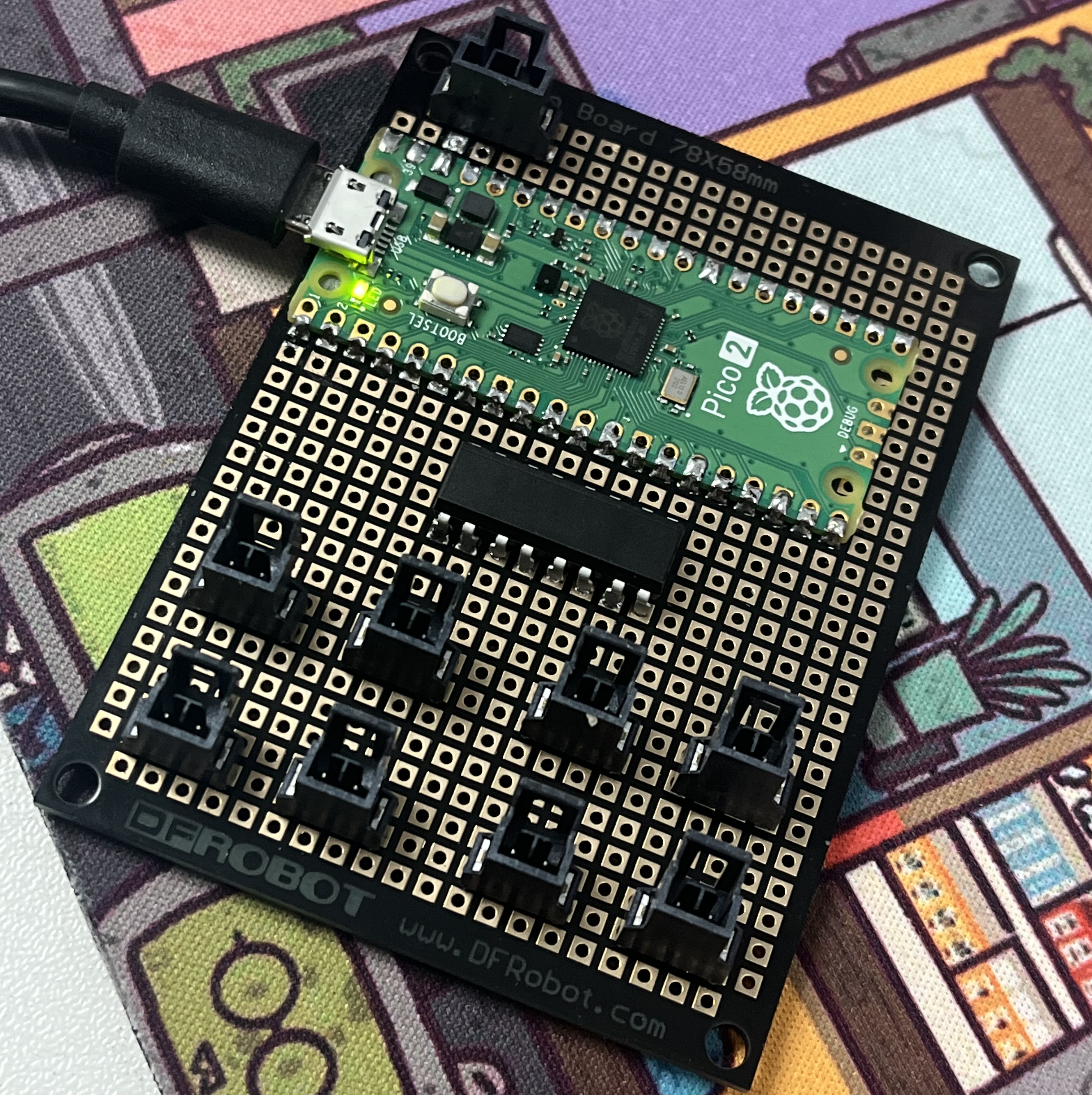
The physical dial input for the room puzzle.
The brains of the translation, handles 2 dials at once.
Used to safely bridge the Pico's 3.3V logic with the room hardware's 5V & 12V logic.
This adapter was built for The Real Escape Canada's Train Robbery room .